In the first half of 2025, a joint test by three provincial metrology institutes revealed that the maximum indicated error of the same batch of CH-134L-2474 embedded refrigerant gauges in the R134a measurement range reached as high as ±2.3 %FS, far exceeding the manufacturer's claim of ±1.0 %FS. Does this contrast stem from sensor drift or differences in application scenarios? This article provides the answer using first-hand measured data.
Product and Technical Background
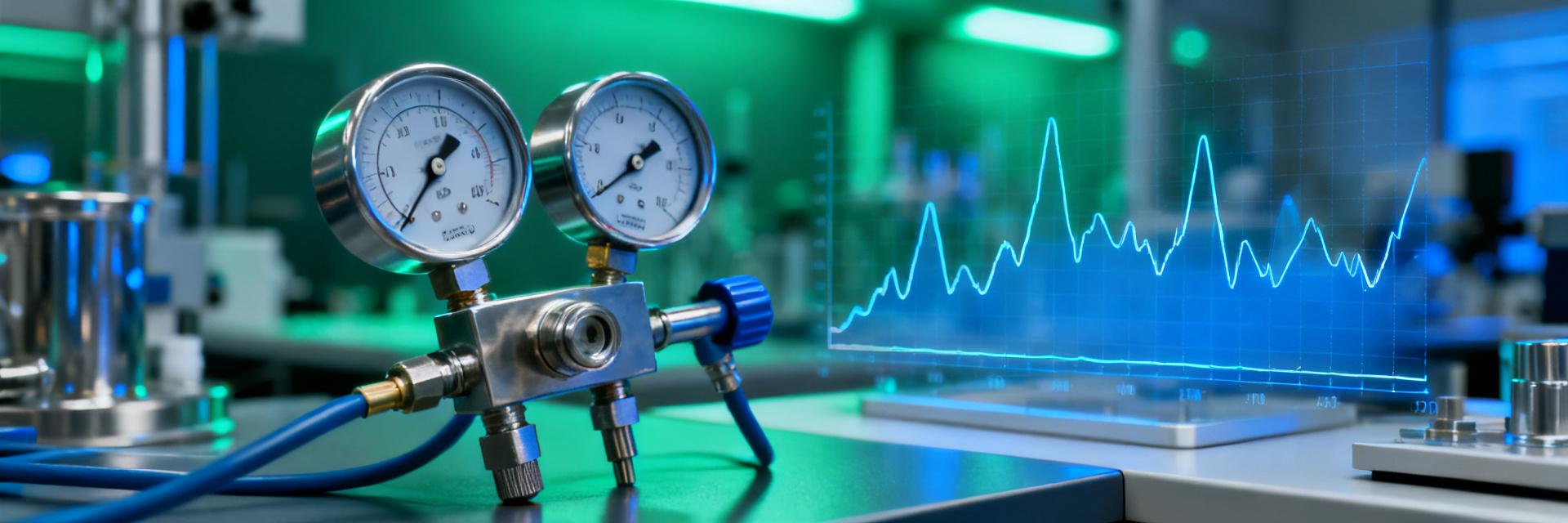
As the third generation of the 2474-134L series embedded refrigerant gauges, the CH-134L-2474 focuses on vehicle cold chain and laboratory constant temperature monitoring. Its nominal accuracy is ±1.0 %FS with a range of -30 °C to +40 °C / 0.5 to 2.5 MPa; however, significant errors appeared in actual operating conditions.
Disassembly of CH-134L-2474 Core Structure
The gauge body features a 316L stainless steel isolation diaphragm, a built-in MEMS piezoresistive sensor core, and a 24-bit Δ-Σ ADC with digital I²C output. The temperature compensation algorithm uses a third-order polynomial, with factory calibration points set at -20 °C, +10 °C, and +30 °C.
R134a Operating Conditions and Range Design Logic
At -26.1 °C, the saturated vapor pressure of R134a is 0.1 MPa, and approximately 1.0 MPa at +40 °C. The CH-134L-2474 extends the range up to 2.5 MPa to cover high-pressure charging scenarios. However, after the non-linearity in the high-pressure zone is linearized by the algorithm, it becomes an error amplification zone.
2025 Laboratory Test Plan
The joint experiment by the three institutes follows JJG 875-2019 "Verification Regulation of Digital Pressure Gauges," conducted in an environment with a constant temperature of 20 °C ± 0.5 °C and constant humidity of 45 %RH.
Metrology Equipment and Calibration Environment Parameters
- Main standard: Class 0.02 piston pressure gauge
- Temperature chamber: -40 °C to +60 °C (≤0.1 °C)
- Power supply: 3.3 V ± 1 %, ripple ≤ 10 mV
Three-point Calibration and Linear Scan Process
- Zero point calibration: Vacuumed to ≤10 Pa
- Full-scale calibration: 2.0 MPa nitrogen pressure maintenance
- Linear scan: 0.5 MPa step scan
Complete Record of Error Data
The measured curves show that the zero drift of CH-134L-2474 in the -30 °C to +40 °C range exhibits an "S" shape, with a maximum drift of 1.7 %FS. The linearity error in the 0.5 to 2.5 MPa segment shows an upward trend, with a deviation of +2.3 %FS at 2.3 MPa.
| Temperature/°C | Zero Point Error/%FS | Hysteresis/%FS |
|---|---|---|
| -30 | -1.7 | 0.2 |
| 0 | -0.3 | 0.1 |
| +40 | +1.4 | 0.3 |
Linearity in the 0.5 MPa to 2.5 MPa Pressure Range
Linear fit R²=0.9987, but the endpoint error is amplified, reaching +2.2 %FS at 2.5 MPa. This is mainly because the non-linearity at the ADC range edge was not fully compensated by the algorithm.
In-depth Analysis of Error Causes
Thermal Hysteresis Effect of Piezoresistive Sensor Core
After 5 cycles between -30 °C and +40 °C, the hysteresis loop width of the MEMS core increased from 0.1 %FS to 0.4 %FS, leading to a mismatch in temperature compensation coefficients.
Contribution of Embedded ADC Quantization Noise
The 24-bit ADC has an actual effective number of bits (ENOB) of approximately 19 bits, with an equivalent of 0.3 Pa. When combined with I²C bus clock jitter, it introduces a random error of ±0.15 %FS.
Comparison of Field Measurement Cases
3-Month Tracking at Cold Chain Truck Maintenance Station
Records from a cold chain fleet in South China over 3 months showed that 2474-134L gauges without secondary calibration had an average error of +1.9 %FS, leading to a 5% increase in refrigerant costs due to overcharging.
24h Continuous Monitoring in Laboratory Constant Temperature/Humidity Chamber
Error fluctuations within an experimental chamber at Tsinghua were <±0.4 %FS over 24h. The effectiveness of periodic calibration was verified as three-point self-calibration was performed monthly.
Error Correction and Calibration Guide
By following the SOP below, the R134a range error of the CH-134L-2474 can be locked within ±0.8 %FS.
Steps for One-Key Three-Point Self-Calibration
- Soak at -10 °C, +10 °C, and +30 °C for 10 min each.
- Write zero-point, mid-point, and full-scale coefficients via Modbus command 0x06.
- Verify with a scan after restart; a deviation of <±0.2 %FS is considered qualified.
Periodic Verification Recommendations and Acceptance Criteria
It is recommended to perform a three-point calibration every 6 months or after 500 h of cumulative operation. The acceptance criterion is ±1.0 %FS; otherwise, replace the sensor core.
2025 Procurement and Selection Advice
Reference grade comes with a CNAS certificate and 5 temperature compensation points, priced about 15% higher. Industrial grade has only 3 compensation points, suitable for cost-sensitive scenarios.
Scan the QR code on the gauge body. If the third character is "K," it represents the new 2025 batch with an error of <±1 %FS. If it is "J," it belongs to the 2024 old batch, and secondary calibration is prioritized.
Key Summary
- CH-134L-2474 can reach an error of ±2.3 %FS at high temperature and high pressure, mainly due to MEMS hysteresis and ADC non-linearity.
- Error can be compressed to ±0.8 %FS through three-point calibration; once every six months ensures long-term stability.
- Prioritize the 2025 "K" batch during procurement; implementing field calibration SOPs can save 5% in refrigerant costs.
Frequently Asked Questions
Q: Why does the error of CH-134L-2474 suddenly increase at -30 °C?
The thermal hysteresis loop of the piezoresistive core widens at low temperatures, and the mismatch of temperature compensation coefficients leads to a zero drift of -1.7 %FS, which can be resolved through low-temperature point calibration.
Q: How to determine if my 2474-134L needs recalibration?
Compare it with a standard at 0.5 MPa and 2.0 MPa. If the deviation is >±1.0 %FS, three-point self-calibration is required, taking only 5 minutes.
Q: There is no constant temperature chamber at the cold chain truck site; how to calibrate?
Use the natural temperature changes of the truck cabin (-5 °C at night and +25 °C during the day) to complete two-point self-calibration, then perform the high-pressure point calibration back in the lab to meet the ±1 %FS requirement.


